

下文主要给各位亲们讲解的是UG10.0绘制立体管道零件的具体操作方法,一定有许多朋友很是期待吧,下面就是UG10.0绘制立体管道零件的教程。
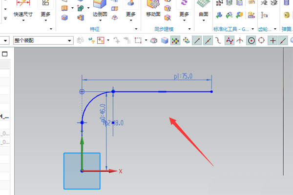
1、绘制弯管,最重要的就是画线,按下图尺寸,绘制需要的线;
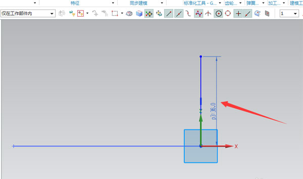
2、以线的端点为基点,创建一个CSYS坐标,等下要根据这个坐标来绘制图形;

3、创建一条垂直的直线,此线的绘图平面要选步骤2所创建的坐标线;
4、绘制如下图的R角线,其半径为18mm,(此线处需要运用制作拐角,以防止其会断开);
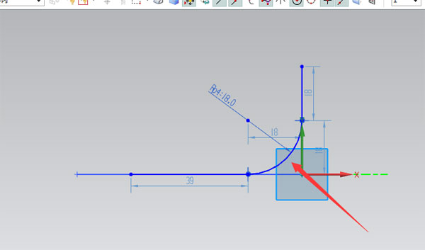
5、通过以上四步绘制的曲线,最终如下图;
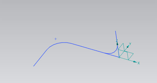
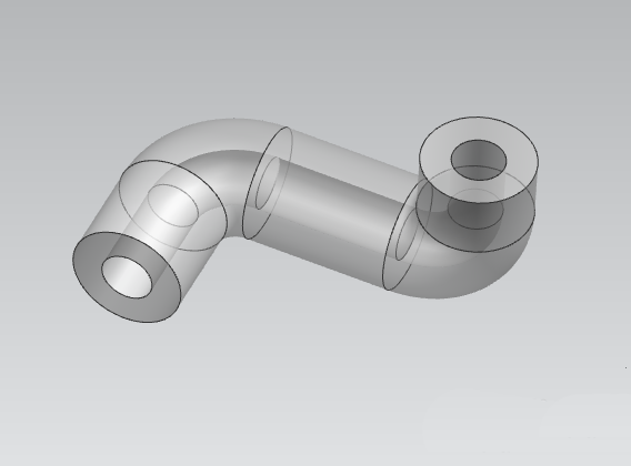
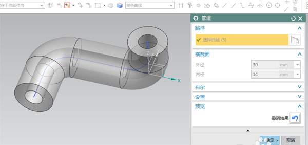
6、选中绘制好的曲线,通过使用管道命令,创建如图1的特征,退出命令后,其零件如图2。

以上就是小编带来的UG10.0绘制立体管道零件的教程,你们都知道了吗?


")
")


语音转文字!新媒体翻译者都有哪些实时语音转文本工具?")


