

很多朋友喜欢使用cad软件绘图,而在今天的文章里,小编就跟大家详细讲讲cad绘制管道立体图的操作教程。
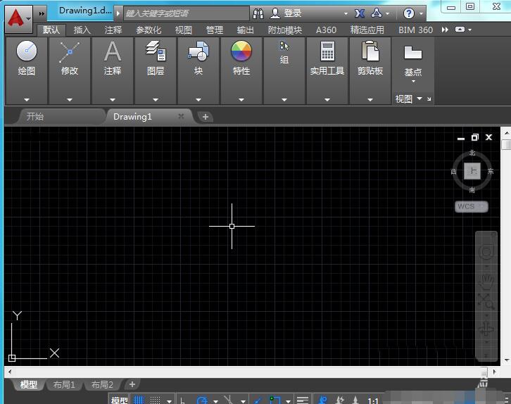
1、打开CAD这款软件,进入CAD的操作界面,如图所示:
2、在该界面内找到直线工具,如图所示:

3、使用直线绘制出主线路,如图所示:

4、再在主线路的基础上在画出分支路如图所示:

5、再在工具箱内找到修剪工具,如图所示:

6、使用修剪命令将多余的线修剪掉,如图所示:

7、再在工具箱内找到文字工具,如图所示:

8、使用文字工具在图中标出管道的直径,最后的管道图就绘制好了,如图所示:

上面就是小编带来的cad绘制管道立体图的操作教程,大家都学会了吗?


")
")


语音转文字!新媒体翻译者都有哪些实时语音转文本工具?")


